Interior Electronics Retrofit: Gauge Cluster and Steering-Wheel Compatibility for the Mazda3 (BM/BN Series)
The Mazda3 BM and BN series (2014-2019) offer exceptional value as a sporty compact sedan and hatchback, but base-model trims often come with less impressive interior equipment. Many enthusiasts want the full-color digital gauge clusters, adaptive cruise control buttons, and audio controls found in higher trims—but paying the premium for those models isn’t always feasible. Fortunately, with proper CAN-bus compatibility knowledge and careful wiring adaptation, you can retrofit these components from donor vehicles or aftermarket sources without triggering diagnostic fault codes.
This comprehensive guide walks you through the entire process—identifying compatible donor parts, mapping the electrical connections, programming the necessary modules, and verifying everything functions as intended.
Understanding the Mazda3 BM/BN Platform Electronics Architecture
Before diving into the retrofit process, you need to understand how the Mazda3’s interior electronics communicate. The BM (2014-2018) and BN (2019) generations share a common controller area network (CAN) architecture, but there are important differences in wiring and module compatibility between model years and trim levels.
The CAN-bus Hierarchy
The Mazda3 uses a multi-node CAN-bus system with three primary networks:
- High-speed CAN (500 kbit/s): Engine management, transmission, brakes, and stability control
- Medium-speed CAN (125 kbit/s): Body control modules, lighting, and climate control
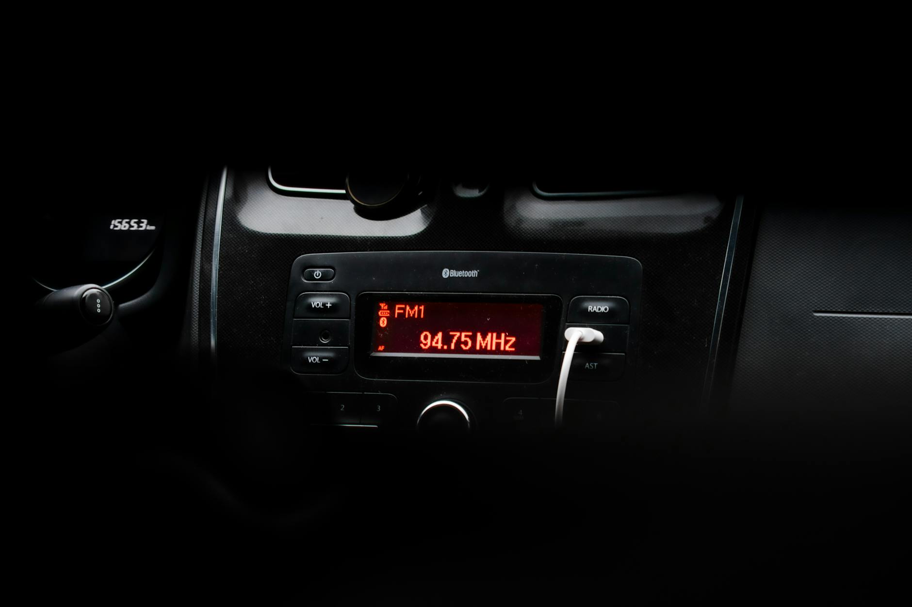
- Low-speed CAN (33.3 kbit/s): Infotainment, gauge cluster, and steering wheel controls
The gauge cluster and steering wheel controls operate on the low-speed CAN bus, which simplifies retrofit compatibility—you’re primarily dealing with one network rather than complex inter-module communication across multiple busses.
Trim-Level Differences
Mazda produced the BM/BP series in multiple trim levels with varying equipment:
| Trim Level | Gauge Cluster Type | Steering Wheel | Advanced Features |
|---|---|---|---|
| Base (GS) | Monochrome LCD | Standard audio buttons | None |
| Sport (GS-S) | Full-color 7-inch | Audio + phone controls | Adaptive cruise |
| Limited (GT) | Full-color with navigation | Full multimedia | Full ADAS suite |
The good news is that physical steering wheels and gauge clusters are largely interchangeable within the same model year range—the challenge lies in ensuring the vehicle recognizes the new hardware and activates all features.
PRO TIP: “Always source donor components from the same model year range (BM to BM or BN to BN) when possible. While physical fitment may work across years, the CAN message definitions can differ, leading to intermittent faults or non-functional buttons.”
Sourcing Compatible Donor Components
Finding the right parts is half the battle. You have two primary paths: harvesting components from a higher-trim donor vehicle or purchasing aftermarket solutions.
OEM Donor Parts
The cleanest approach is sourcing a complete gauge cluster and steering wheel from a wrecked or parted-out higher-trim Mazda3. Here’s what to look for:
Gauge Cluster Requirements:
- Matching model year (2014-2018 for BM, 2019 for BN)
- Same transmission type (automatic or manual clusters differ)
- Same engine displacement if possible (some clusters display engine-specific information)
- All mounting hardware and bezel
Steering Wheel Requirements:
- Matching model year
- Same airbag connector configuration (pre-facelift versus facelift)
- Matching button configuration for your desired features
- Control module built into steering wheel (most are integrated)
Check junkyards, online parts marketplaces, and Mazda enthusiast communities for donor parts. Expect to pay $200-500 for a complete gauge cluster and steering wheel with wiring harness.
Aftermarket Solutions
Several companies offer upgraded gauge clusters and steering wheel solutions:
Digital Gauge Clusters:
- Various manufacturers produce replacement clusters with enhanced functionality
- Some offer programmable displays with custom layouts
- May require additional CAN-bus adapters
Steering Wheel Control Modules:
- Aftermarket wheels with integrated controls
- Universal control modules that interface with factory infotainment
- Requires verification of steering wheel angle sensor (SAS) compatibility
PRO TIP: “Test all electrical connections before final installation. Connect the donor gauge cluster and steering wheel to the vehicle wiring harness with the vehicle in accessory mode (engine off) to verify basic functionality before committing to full installation.”
Wiring Diagrams and Electrical Adaptation
The heart of a successful retrofit lies in correct wiring connections. While many components share common connectors, you’ll need to fabricate adapter harnesses or splice into existing wiring.
Gauge Cluster Connector Pinout
The BM/BN gauge cluster uses a 20-pin connector with the following key connections:
Power and Ground:
- Pin 1: Battery constant power (12V)
- Pin 2: Ignition power (12V when in ACC or run)
- Pin 3: Ground
CAN-bus Connections:
- Pin 4: CAN-low
- Pin 5: CAN-high
- These connect to the vehicle’s low-speed CAN network
Illumination:
- Pin 6: Dashboard backlight power
- Pin 7: Backlight ground (dimming)
Specific Signals:
- Pin 10: Vehicle speed signal (from ABS module)
- Pin 11: Engine RPM signal
- Pin 12: Fuel level signal
- Pin 13: Coolant temperature signal
The exact pinout varies by model year and trim—always verify with a multimeter or factory service manual.
Steering Wheel Connector Pinout
The steering wheel connects through a clockspring (also called a cable reel) to the vehicle wiring. Key connections include:
- Airbag connector: Yellow, two-pin connector for driver airbag
- Button assembly: Multiple-pin connector for audio/cruise/phone buttons
- Horn connection: Two-wire connection for horn activation
- Steering angle sensor (if equipped): Three-wire connection for ADAS functions
The steering wheel buttons communicate over CAN-bus in most configurations—the buttons themselves are just switches that signal to the instrument cluster or head unit.
Adapter Harness Fabrication
To connect donor components, you’ll need to fabricate an adapter harness. This typically involves:
- Obtaining the connector housings from the donor vehicle or electronics supplier
- Running new wiring or adapting existing harness sections
- Ensuring proper pin assignments match your specific vehicle configuration
Use TXL-grade wire (薄壁乙烯基绝缘) for durability and heat resistance. Solder all connections and use heat-shrink tubing for protection.
PRO TIP: “Label every wire during disassembly. Take photos of connector orientations before disconnecting anything. Trust us—you’ll thank yourself later when it’s time to reassemble.”
CAN-bus Adaptation and Fault Code Prevention
This is the critical phase: ensuring the vehicle recognizes the new components without triggering diagnostic trouble codes (DTCs).
The Body Control Module Programming
The BCM (body control module) in the Mazda3 maintains a database of expected equipment. When you install new hardware, the module may detect a mismatch and store fault codes. Here’s how to handle this:
Method 1: Complete Module Swap
- Swap the BCM along with the gauge cluster and steering wheel
- This provides perfect compatibility but requires programming
- Must be done by a dealer or authorized tool
Method 2: CAN-bus Emulation
- Use a CAN-bus adapter device that translates messages
- Some aftermarket devices can “fake” the original signals
- More complex to configure but flexible
Method 3: Software Modification
- Reflash the BCM to recognize new equipment
- Requires specialized software and knowledge
- Not recommended for DIY installers
Common Fault Codes and Solutions
After installation, check for these common DTCs:
| DTC | Meaning | Solution |
|---|---|---|
| U0100 | Lost communication with ECM/PCM | Verify CAN connections, check for opens |
| B1000 | Instrument cluster malfunction | Check cluster power and ground, verify CAN |
| B1151 | Steering angle sensor malfunction | Verify SAS connections, calibrate if needed |
| U3000 | Control module malfunction | Check for short circuits in wiring |
Use an OBD-II scanner capable of reading manufacturer-specific codes (like Forscan or Mazda IDS) to clear codes and verify system health.
Steering Angle Sensor Calibration
If you’re installing a steering wheel with adaptive cruise control or other ADAS features, you’ll need to calibrate the steering angle sensor:
- Center the steering wheel perfectly straight
- Using Forscan or equivalent software, navigate to the SAS calibration procedure
- Follow the on-screen prompts to complete calibration
- Verify proper operation through test driving
Step-by-Step Installation Procedure
With the background complete, here’s the installation sequence:
Phase 1: Preparation
Tools Required:
- Basic hand tools (sockets, wrenches, screwdrivers)
- Soldering iron and supplies
- Multimeter
- Diagnostic scan tool (Forscan recommended)
- Wire strippers and crimpers
- Heat shrink tubing
Safety First:
- Disconnect the negative battery terminal
- Wait 10 minutes before working on airbag components (capacitor discharge time)
Phase 2: Removal of Existing Components
- Remove the negative battery terminal
- Remove the lower dashboard trim panel
- Remove the gauge cluster bezel and cluster (disconnect connector)
- Remove steering wheel cover plates (two screws behind, accessible with wheel pulled)
- Remove the steering wheel (mark alignment first)
- Disconnect all connectors, labeling each
Phase 3: Donor Component Preparation
- Inspect donor gauge cluster for any damage
- Clean all connectors and test basic function (connect to power temporarily)
- Verify donor steering wheel button function
- Fabricate adapter harness if needed
Phase 4: Installation of New Components
- Install donor gauge cluster, secure all mounting hardware
- Connect all electrical connectors (verify correct orientation)
- Install steering wheel, ensuring proper mating of airbag connector
- Reconnect battery negative terminal
Phase 5: Testing and Calibration
- Enter ignition ON mode (engine off)
- Verify gauge cluster illuminates and displays all information
- Test all steering wheel buttons
- Scan for diagnostic trouble codes
- Clear any codes stored during installation
- Perform steering angle sensor calibration if necessary
- Test drive to verify all functions operate correctly
Troubleshooting Common Issues
Even with careful installation, issues can arise. Here’s how to address them:
Gauge Cluster Not Illuminating
Check in this order:
- Power connections (12V and ground)
- Fuse for instrument cluster
- Backlight fuse
- Connector seating
Steering Wheel Buttons Not Responding
Verify:
- Clockspring proper installation and connection
- CAN-bus communication (scan for related codes)
- Button continuity with multimeter
- Cluster recognizes wheel input
Fault Codes Will Not Clear
Potential causes:
- Physical fault still present (short, open)
- Module incompatibility
- Missing required peripheral (sensor, switch)
Intermittent Operation
Usually indicates:
- Poor connector contact (clean and treat)
- Ground issue (verify chassis ground)
- CAN-bus termination problem
Conclusion
Retrofitting a premium gauge cluster and multifunction steering wheel into your base-trim Mazda3 is entirely achievable for patient DIY mechanics willing to invest in proper diagnosis tools and research. The key to success lies in understanding the CAN-bus architecture, sourcing compatible components, and meticulously executing the wiring connections.
While the process requires attention to detail and some investment in tools and parts, the result is a significantly upgraded interior that adds both functionality and value to your Mazda3. The full-color gauge cluster provides better readability and a premium feel, while the multifunction steering wheel enables hands-free control that enhances daily driving convenience and safety.
Take your time, verify each connection, and don’t skip the testing phases. Your patience will be rewarded with interior electronics that function as well as anything from the factory—often better.
PRO TIP: “Document your entire build with photos and notes. Your build thread becomes an invaluable resource for the next enthusiast tackling this project—and it’s incredibly satisfying to look back at what you accomplished.”
Ready to tackle your Mazda3 interior retrofit? Start by gathering the necessary tools and sourcing your donor components. The detailed preparation you put in upfront will pay dividends during the installation process.